New Style PRECISION TOOL GROUP
Adapter Packages 8040, 8030 or 8020
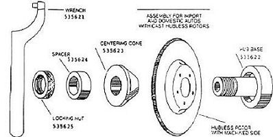
Adapter Kits 8011, 8012, & 8013 For Hubless & Composite Rotors, Drums, & Flywheels.
These Accu-turn brake lathe adapter sets are for use with applications that include cast hubless rotors,
composite rotors, hubless drums, and flywheels. The flange plates included simulate actual vehicle
mounting. These sets may be used on any lathe with a one inch arbor.
Before you begin:
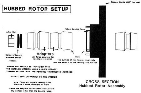
It is critical in any machining operation that all contact
surfaces on the adapters and mounting hardware, as well as the rotor, drum, or flywheel are perfectly
clean with no rust, filings or trash, and free from nicks or burrs. For example a .001 thick lathe
filing between an adapter and the rotor will create .003-.005 run out in the machined rotor.
 Figure 1 - Spring and Adapter
 |
Spring mounting:
It is very important that the spring be placed over the shoulder in the flange plate and twisted counterclockwise
to lock into position (Figure 1). When positioned properly, the spring is held in place on the
flange and will not fall onto the arbor. Failure to do so will result in the spring keeping the cone from
recessing far enough into the flange plate for the rotor to contact properly.
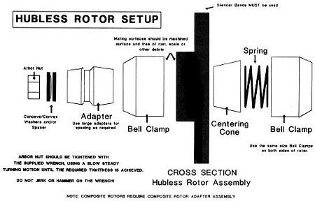
 Figure 2 - Typical Hubless
Rotor Setup |
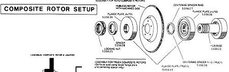
 Figure 3a - Typical
Composite Rotor Setup |
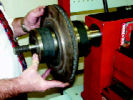 Figure 3b - Spring
and Adapter
|
Typical rotor mounting: See Figures 2, 3a, & 3b.
- Determine which flange plate best fits the inside hat section of the rotor. Always use the largest
flange plate possible, however the flange plate must contact only the flat machined surface of the
rotor. NOTE: Using the largest flange plate possible is extremely critical when machining composite
rotors.
- Place the appropriate flange plate on the arbor and install the spring.
- Select the centering cone that best fits the rotor center hole and place on the arbor wide end first.
- Slide the rotor onto the arbor, locating the center hole over the centering cone. Push the rotor and
cone back against the spring and flange plate.
- Slide the largest remaining flange plate which fits the rotor onto the arbor.
- Fill out the arbor with arbor spacers as required to secure the entire rotor assembly to the arbor.
- Tighten the arbor nut.
Important: Any rust, filings, trash, nicks or burrs on the rotor, or contact surface of any adapters, will
distort the arbor making the end of the shaft move up and down. If this is happening, the entire assembly
must be dismounted and all mounting surfaces checked and cleaned before the rotor is machined.
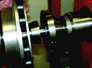 Figure 4 - Small Hubless
Rotor Setup |
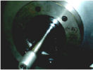 Figure 5a - Large Hole
Rotor Setup |
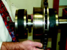 Figure 5b - Large Hole
Rotor Setup |
Odd configured cast hubless rotors:
- Rotors that are too small on the inside to accept the smallest flange plate.
See Figure 4.
- Cone #460573 is reversible and can be used as a flange plate. NOTE: This is the only cone
which may be used in this manner.
- Place the 460573 cone on the arbor and install the spring.
- Proceed as from step 3 above.
- Rotors with extremely large center holes. The centering cone needed is too large for the flange
plate which fits the inside of the rotor. See Figures 5a & 5b.
- Install the appropriate flange plate on the arbor. Do not install the spring.
- Slide the rotor onto the arbor. Select the centering cone that best fits the rotor center hole and
place on the arbor small end first.
- Install the spring into the appropriate flange plate and slide onto the arbor.
- Proceed as from step 3 above.
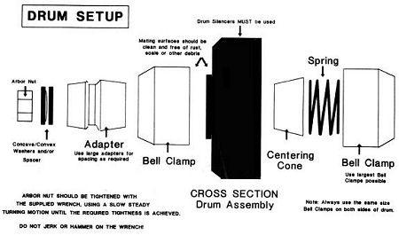
Figure 6 - Hubless Drum
Setup |
Figure 7 - Small Hubless
Drum Setup |
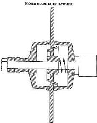
Figure 8 - Typical Flywheel
Setup |
Typical drum mounting: Use the same basic techniques as described above for typical rotor mounting.
See Figure 6. Use the largest flange plate possible inside the drum which will contact the flat inner
surface and allow clearance for the boring bar. On smaller drums which do not allow clearance for the
boring bar, use the 460573 reversible cone on the inside as above for small rotors. See Figure 7.
Typical flywheel mounting: Use the same basic techniques as described above for typical rotor
mounting. Use the largest mounting adapter possible on the inside and outside which will contact the
machined surfaces. See Figure 8. NOTE: Flywheels may have very small machined mounting surfaces.
It is extremely important that the mounting adapters only contact flat machined surfaces.
|